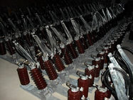
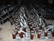
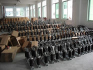
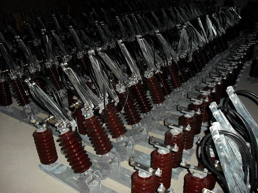
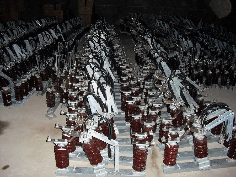
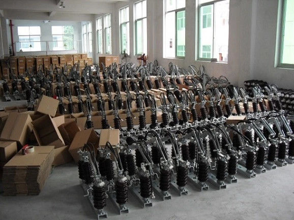
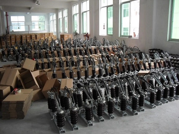
GW4-33 2000 Manual Control Switch Rocking Disconnectors
The rating of the complete isolator shall be as follows: -
Rated voltage
36 kV
Rated frequency
50 Hz
Rated lightning impulse withstand voltage
200 kV
Rated power frequency withstand voltage, dry
95 kV
Rated normal current
400 Amps
Rated short time withstand current for 3 sec, min.
18.0 kA
Minimum creepage distance of insulators
900 mm
These disconnectors are , no load switching devices
which physically isolate the lines. They are designed for
horizontal outdoor application and can also be designed
for vertical installation. For earthing and closing of
switchyard portions of the installation, the earthing
switches are provided on disconnector. If required.
The following documents were referred to during the preparation of this specification. In case of conflict, the provisions of this specification shall take precedence.
IEC 129:1975: Alternating Current Disconnectors (Isolators) and Earthing Switches
IEC 60694:2002: Common Specifications for High Voltage Switchgear and Controlgear
BS 729: Hot dip galvanized coating on iron and steel articles
IEC62271-102
Isolator (Disconnector) - a mechanical switching device which provides, in the open position, an isolating distance in accordance with Electrical Safety requirements.
SERVICE CONDITIONS
The isolator shall be suitable for continuous operation outdoors in tropical areas at altitudes of up to 2200m above sea level, humidities of up to 90%, average ambient temperature of +30ºC with a minimum of -1ºC and a maximum of +40ºC and heavy saline conditions along the coast.
4.2. DESIGN AND CONSTRUCTION
4.2.1 The Isolator, Solid Link shall be designed and constructed in accordance with IEC 129 and IEC 60694.
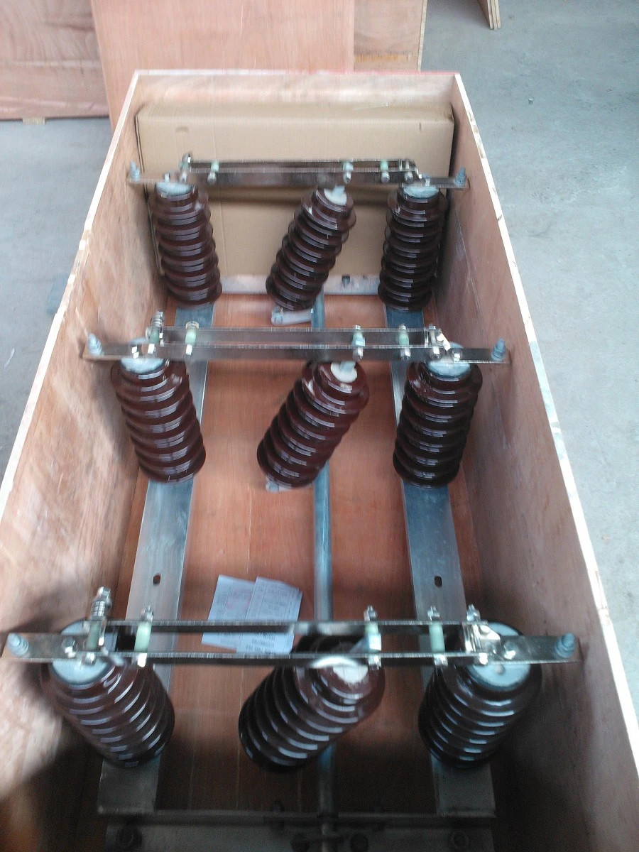
4.2.2 The isolating link shall be of the vertical opening, designed for single phase manual operation. It shall be easily removed and replaced by using a portable operating rod.
4.2.3 The isolating link shall incorporate double porcelain insulators to suit voltage requirements and mounted on hot dipped galvanised steel under base suitable for vertical mounting.
4.2.4 The isolating link shall be arranged so that each unit is mounted independently on an angle bracket. It shall be supplied complete with the angle bracket and accessories suitable for mounting on 'U' type steel channel. The drawings to be submitted shall indicate all the applicable mounting positions.
4.2.5 The isolator shall be designed such that in fully open position, it shall provide adequate electrical isolation between the contacts on each phase. It shall conform to the requirement as single point isolation for safety.
4.2.6 All steel parts shall be hot dip galvanized to BS 729. The minimum coating of galvanizing required is 80 microns.
4.2.7 The solid link shall be removable from the mounting by use of operating rod.
4.2.8 All current carrying parts of the isolator shall be made of high conductivity material.
4.2.9 The isolator shall be fitted with clamp connectors for Aluminium (ACSR) conductor of Aluminium (ACSR)conductor of up to 18.2mm diameter.
The rating of the complete isolator shall be as follows: -
Rated voltage
36 kV
Rated frequency
50 Hz
Rated lightning impulse withstand voltage
200 kV
Rated power frequency withstand voltage, dry
95 kV
Rated normal current
400 Amps
Rated short time withstand current for 3 sec, min.
18.0 kA
Minimum creepage distance of insulators
900 mm
System Voltages 132kV
1 System: 50 Hz, 3phase
2 Neutral Point Earthing Solidly Earthed Earthing Resistor
3 Nominal voltage of networks 132kV
4 Highest system voltage as defined by IEC - 38 145kV
5 Short circuit not less than [MVA] N/A
6 Short circuit and earth fault current, symmetrical r.m.s. value not less than N/A
7 Thermal short circuit current, 1 second not less than 31.5 kA
8 Dynamic Peak current not less than 80 kA
9 Continuously rated currents of Isolating Switches: 1 600 A
10 Isolation Voltage according to IEC - 71
10 a - Switching Surge withstand voltage
Phase to earth 275 kV
- Longitudinal impulse component of combined test 325 kV
10 b - Lightning Impulse withstand voltage 1.2/50 micro-s
To earth and between phases 650kVp
Across the isolating distance of isolating switches 750 kVp
10 c - Test voltage at power frequency 1 minute, dry and wet
(at sea level)
To earth and between phases (r.m.s.) N/A
Across the isolating distance of isolating switches N/A
11 For the design and erection of the conductors in the switchyard the following minimum distance shall be observed:
11a Phasetoground [mm] 1 500
11b - Phasetophase 2 330
11c Busbars phasetophase 3 500
11d Height to live parts above ground 5 500
11e Height to live parts above ground at
service/transportation strips [mm] 5 500
11f - Lowest part of insulators above ground [mm] 3 500
12 Maximum temperature rise of conductors
above ambient temperature (45oC) 40oC
13 Maximum wind pressure on conductors and cylindrical objects 430N/m2
14 Maximum wind pressure on flat surfaces 820N/m2